
Quick Start: Deployment, Sign-In, and First Detection
How would you like to start?
Expand the steps for your path below. Computer previews do not require device static-IP setup.
| Item | Details |
|---|---|
| Who this is for | First-time CosmoEdge users, deployment engineers, and developers |
| What you will accomplish | Deploy or connect to the system, configure device network and time, add video, assign an algorithm, and verify its output |
| Prerequisites | Docker is installed on an x86 host, an Apple Silicon Mac has the Docker Desktop Preview environment, or a CosmoEdge edge device is provisioned |
| Estimated time | About 15–30 minutes for a native x86 first build; Mac amd64 emulation can take longer; about 15–25 minutes for a provisioned device |
| Device required | Choose an x86 Docker host, an Apple Silicon Mac Preview, or a provisioned edge device; a camera is not required for the first test |
| Final acceptance result | The channel is running, Live Display shows the algorithm overlay, and Event Center contains a matching event or count result |
The goal is not merely to open the UI. It is to complete a verifiable first detection:
- Make CosmoEdge reachable through the x86 Docker, macOS Preview, or edge-device path.
- For an edge device at its default static address, configure the computer first, then sign in and set the device network and time.
- Add an offline test video.
- Assign a scenario task and start analysis.
- Verify the output in Live Display and Event Center.
Changing the default password, setting the device network, and correcting device time are required before production use. The people-counting walkthrough later on this page is a complete additional exercise and does not block the first No Safety Helmet acceptance test.
1. Deploy or Connect to CosmoEdge
Computer preview: Linux, Windows and Mac Preview
1.1 Path A: Docker on an x86 Host
Use this path on a Linux x86_64 host. On Windows, use docker-compose.x86.windows.yml. Apple Silicon Macs use the separate Preview path in the next section.
An earlier validated setup used Ubuntu 22.04.2, an Intel Core i9-13900F, 64 GB of memory, Docker 29.1.3, and Docker Compose v5.1.4. This is a recorded validation environment, not a minimum requirement. Use the root README, the current Compose files, and the resource requirements of your selected models as the current source of truth.
Docker Compose V2 uses docker compose. If the host still uses the standalone legacy Compose binary, replace docker compose with docker-compose.
Get the source from the GitHub source of truth:
git clone https://github.com/cosmo-wander-ai/cosmo-edge.git
cd cosmo-edge
For networks in mainland China, use the project-maintained Gitee mirror instead:
git clone https://gitee.com/cosmo-wander-ai/cosmo-edge.git
cd cosmo-edge
Linux:
docker compose -f docker-compose.x86.yml up -d --build
docker compose -f docker-compose.x86.yml ps
Windows PowerShell:
docker compose -f docker-compose.x86.windows.yml up -d --build
docker compose -f docker-compose.x86.windows.yml ps
The first build downloads dependencies and compiles the project. Duration depends on the network and host.
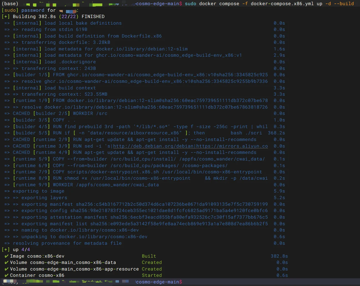
Success conditions:
docker compose ... psreports the services asUporrunning;http://127.0.0.1:8080opens on the host;- for remote access, replace
127.0.0.1with the x86 host IP and allow TCP 8080 through the host firewall.

1.2 Path B: Apple Silicon macOS Preview
If you have not obtained the repository yet, run the following first. Skip this step if you are already in its directory:
git clone https://github.com/cosmo-wander-ai/cosmo-edge.git
cd cosmo-edge
The Mac path uses an isolated linux/amd64 Docker Preview. Read its admission, licensing, and capability boundaries, then run:
./scripts/macos-docker-preview.sh doctor
./scripts/macos-docker-preview.sh up
./scripts/macos-docker-preview.sh status
When healthy, open http://127.0.0.1:8080 on the same Mac. This path is for single-video local evaluation; it is not a native macOS binary, a Sophon or Rockchip NPU deployment, or production performance evidence.
Provisioned device: connect network and power
1.3 Path C: A Provisioned Edge Device
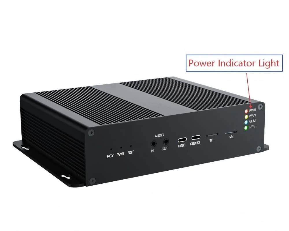
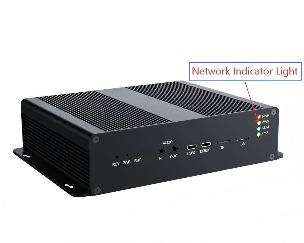
This section demonstrates first connection using a provisioned BM1688 device. Follow the delivery instructions for other models; see the platform support table. The images show an earlier BM1688 dual-Ethernet device. Use the actual label and delivery list for its enclosure, connectors and specifications.
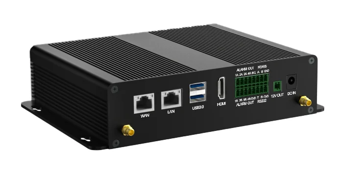
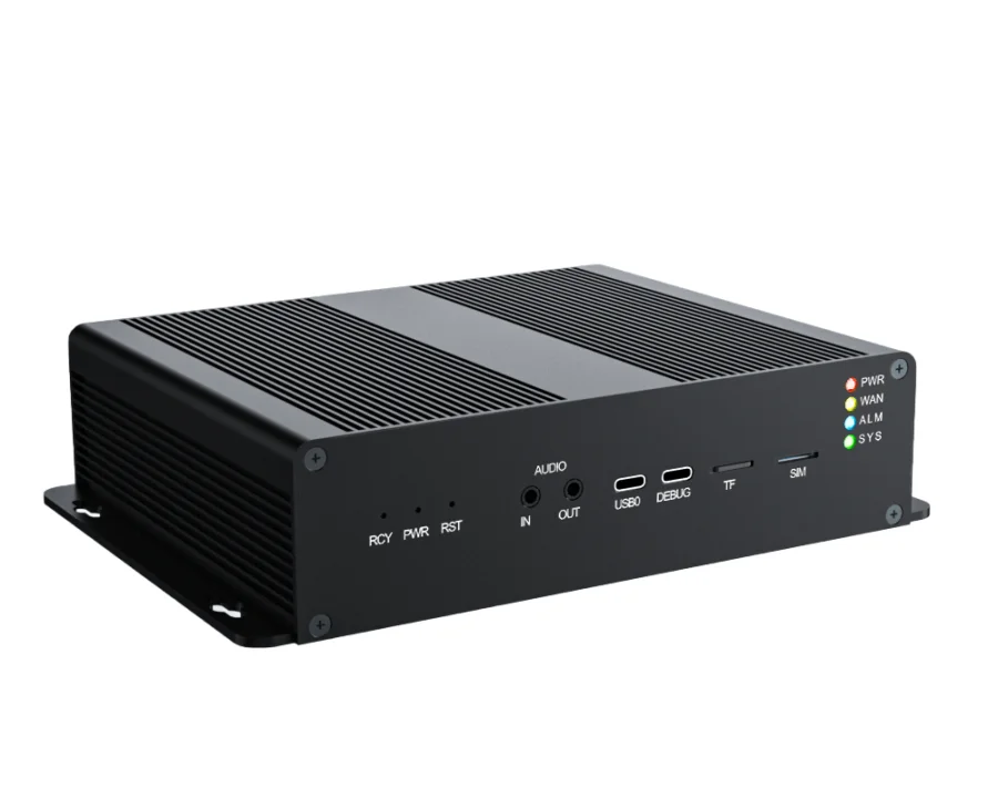
The earlier example device had the following advertised configuration. It is retained to identify that model, not as a universal CosmoEdge hardware requirement:
| Component | Earlier example specification |
|---|---|
| Processor | Sophon BM1688 |
| Host CPU | 8-core ARM Cortex-A53, up to 1.6 GHz |
| Memory | 8 GB LPDDR4 |
| Storage | 64 GB |
| AI compute | Advertised 16 TOPS |
| Network | Two 10/100/1000 Mbps adaptive Ethernet ports |
| Other I/O | Two USB 3.0, one USB Type-C, one HDMI, one TF, and one SIM slot |
The open-source software does not require a hardware purchase. For international purchases of ready devices, contact us by email; international online checkout is not currently available. Explore hardware configurations or use your own compatible hardware. Contact hello@cosmowander.ai for purchase enquiries or to discuss project deployment.
Connect Network and Power
Connect an Ethernet cable from the device to a router, switch, or the setup computer. A direct computer-to-device connection is recommended for initial setup because it removes DHCP, VLAN, and firewall variables.
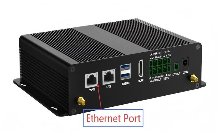
Connect the matching power adapter.
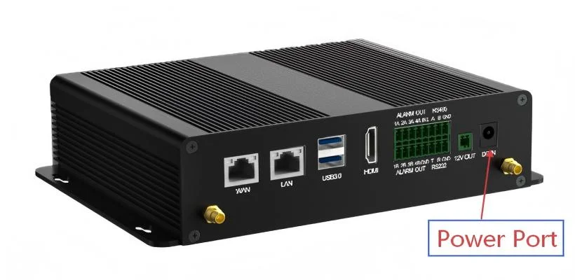
Wait about 60 seconds after power-on. On the example unit, PWR remains lit and the network indicator flashes during traffic. Indicator colors and positions are model-specific.
Configure a Static Address on a Directly Connected Computer
The default address is not a DHCP lease
The current BM1688 release package uses 192.168.100.1 with subnet mask 255.255.255.0 by default. For a direct connection, first assign the computer an address such as 192.168.100.10/24. Do not assign 192.168.100.1 to the computer, because that would create an IP conflict.
On Windows:
Open Settings or Control Panel → Network and Internet → Network Connections / Change adapter settings, then select the Ethernet adapter connected to the device.
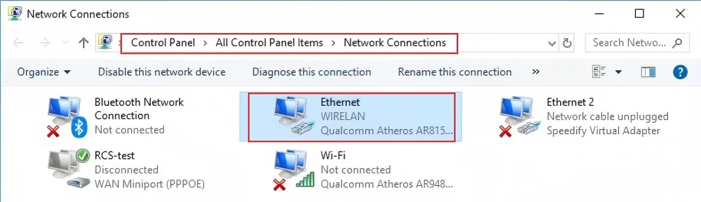
Open the adapter properties and select Internet Protocol Version 4 (TCP/IPv4).
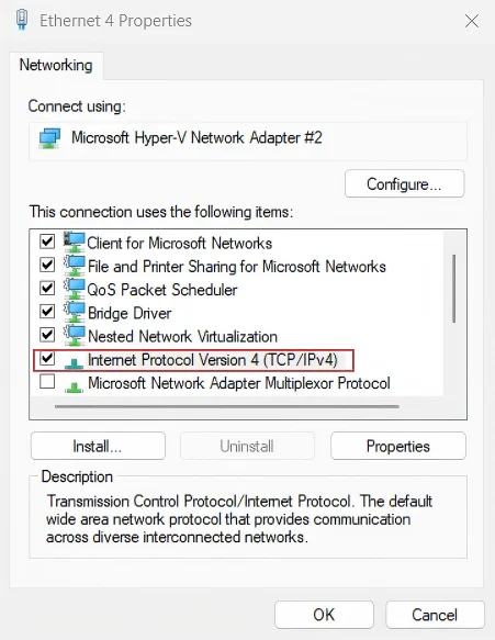
Select manual addressing, enter an unused
192.168.100.xaddress and subnet mask255.255.255.0, and save. A gateway and DNS server are not required for direct setup.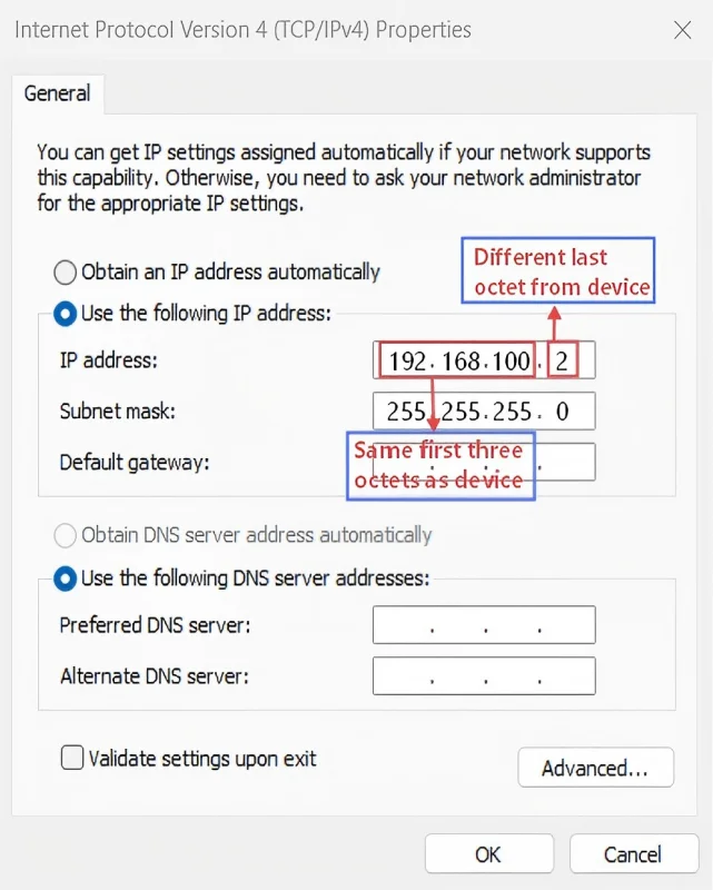
The goal is the same on macOS or Linux: assign an unused 192.168.100.x/24 address only to the adapter connected to the device. Record the original settings so that they can be restored after the device is moved to the production LAN.
Deploy on your edge hardware
Check platforms and installation paths, confirm the target chip and base system, then follow the deployment guide. The package must match your chip and prepared Linux environment; it is not an operating-system image for arbitrary hardware.
After installation, confirm that the console is reachable and the models and scenario for this example are available, then continue with sign-in and first detection below.
2. Sign In and Complete Initial System Settings
2.1 Open the Sign-In Page
- x86 on the same host:
http://127.0.0.1:8080 - remote x86 host:
http://<host-ip>:8080 - BM1688 device at its default address:
http://192.168.100.1 - device whose network has been changed:
http://<current-device-ip>
Use a current Chrome or Edge browser. Initial credentials are:
- Username:
admin - Password:
admin
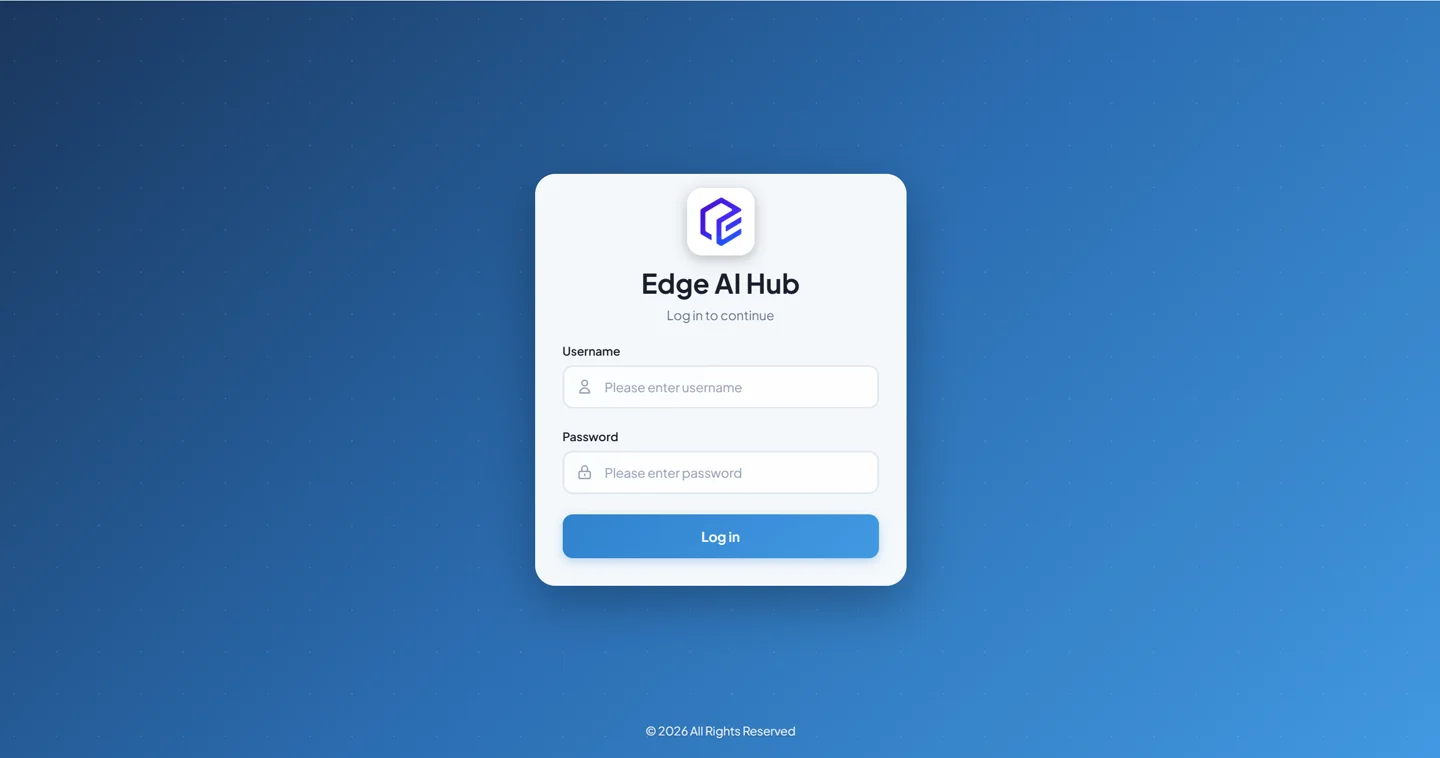
After sign-in, the system home page or runtime overview should appear. Change the default password after the first successful sign-in.
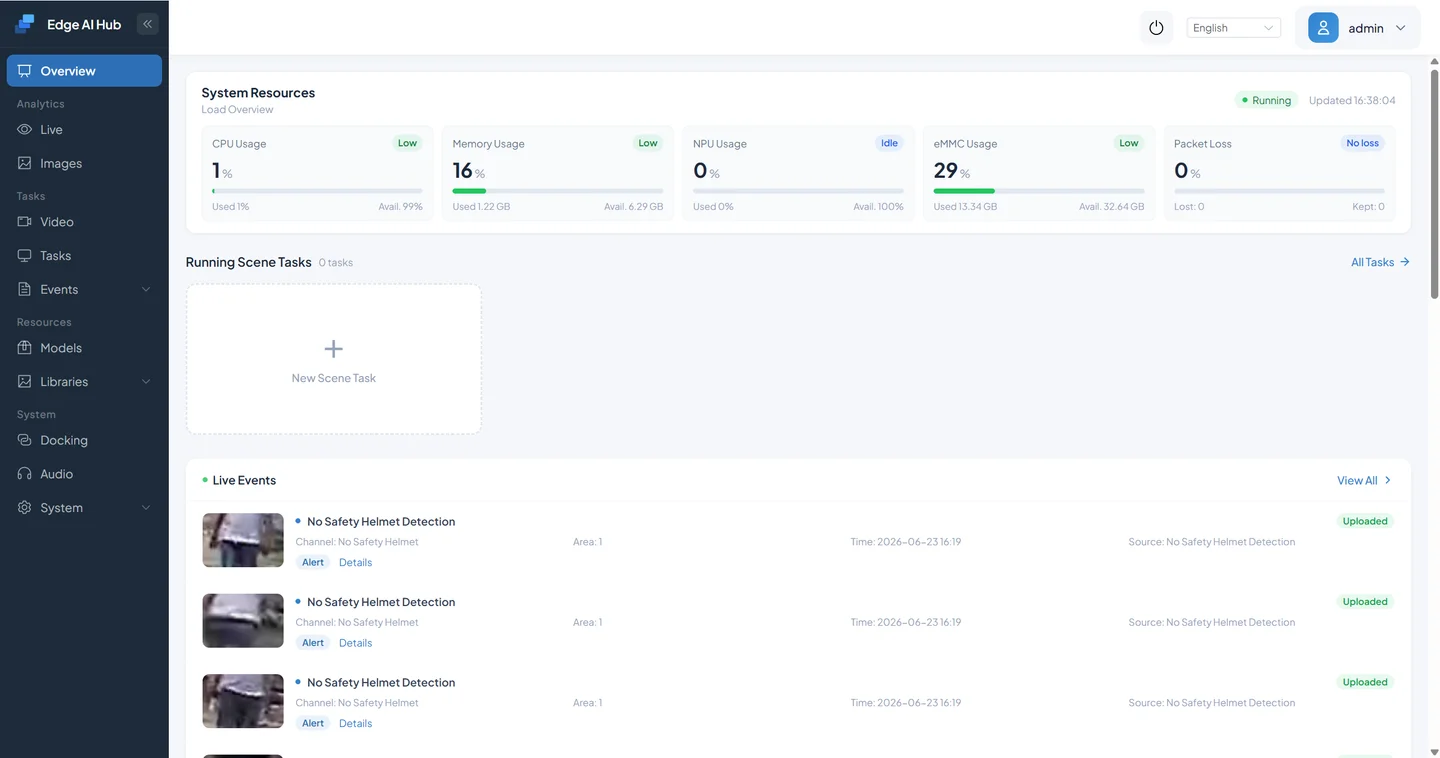
The home page provides a quick view of resources such as CPU, memory or accelerator memory, NPU, storage, and network health. Labels differ by hardware backend. These indicators help diagnose load and health; they are not by themselves business-result acceptance.
2.2 Correct Device Time
Event queries, recordings, and logs all depend on correct time. When the device is directly connected and cannot reach NTP, open System Management → System Settings → Time Settings, select manual calibration, and use Sync with PC. Once the device is on a network, a reachable NTP server is preferable for production.
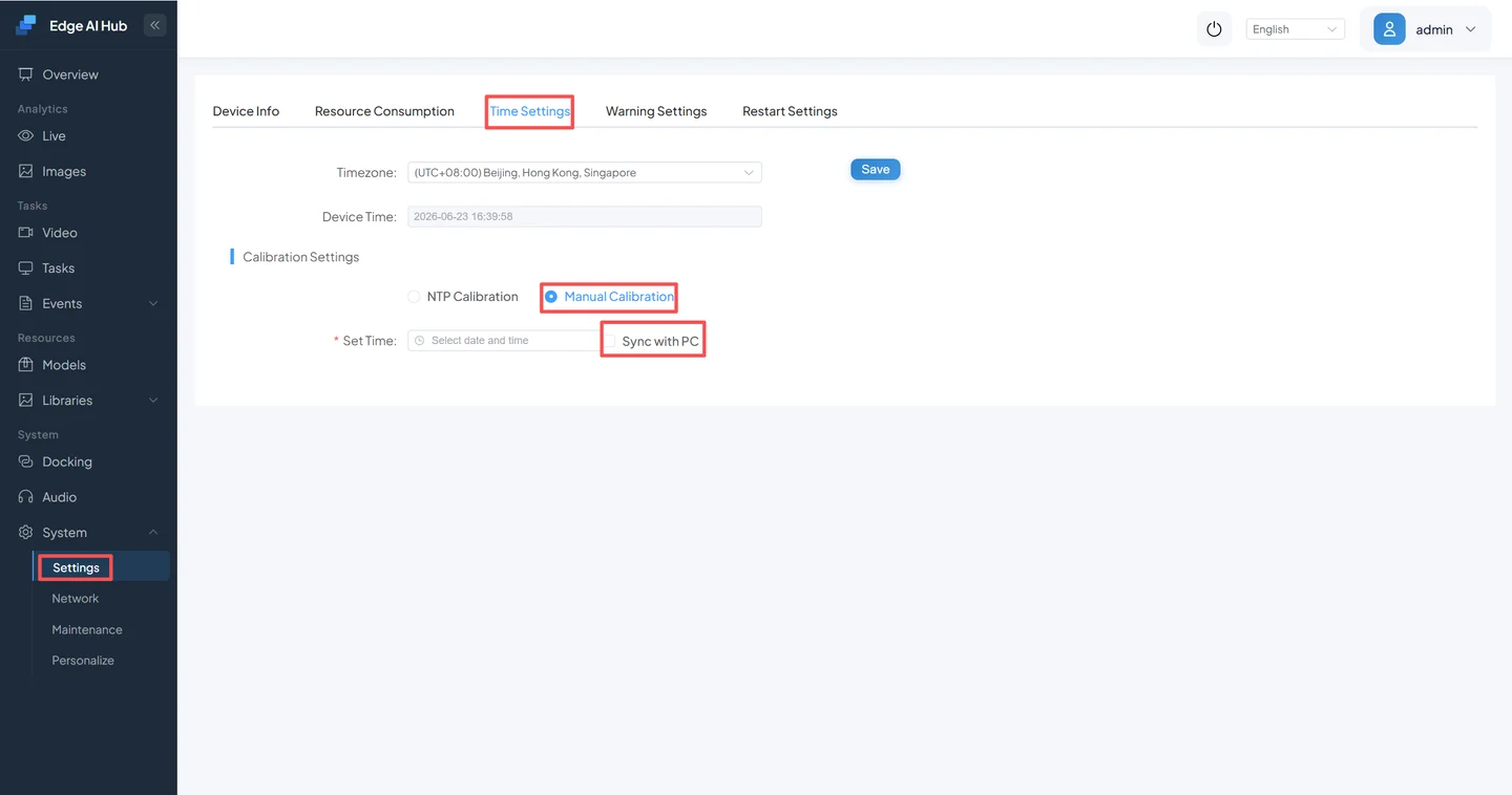
Success condition: device time and time zone match the deployment site, and subsequent events have the same time as the setup computer.
2.3 Move the Device to the Production LAN
If the device must reach cameras, NTP, or external services, open System Management → Network Settings. Assign an unused reserved IP on the production LAN and enter the correct subnet mask, gateway, and DNS servers.
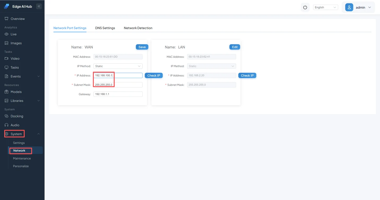
Before saving:
- Record the old address, new address, subnet mask, gateway, and DNS servers.
- Confirm that the new address is unused and that the setup computer can reach the new subnet.
- Save, wait for networking to restart, then sign in through the new address.
- If the computer used a temporary
192.168.100.xaddress, restore its original network settings.
The old address normally stops responding
After the network change takes effect, 192.168.100.1 will normally be unreachable. Move the computer to the new subnet and try the new address before considering a factory reset.
If the page is unreachable, check in this order: computer and device subnet, cable and link indicators, proxy settings, address conflicts, http versus https, and whether a VPN route is taking priority over the directly connected adapter.
3. Add the Test Video
This example uses the “No Safety Helmet” scenario, a person detector and a helmet classifier. Default x86 and Mac Preview builds use the repository’s ONNX example resources. Mac Preview covers a single offline stream and does not provide local VLM inference. For a provisioned device, confirm the chip-specific models and scenario in its delivery list.
If the scenario is missing, check the model resources and confirm the installed assets match your platform. For your own models, follow the integration guide. Template files do not contain model weights.
Download the safety-helmet sample video (MP4, 19.1 MiB)
Alternative: fixed-version GitHub download. If you cloned the repository, you can use the local file below.
The repository contains a reproducible safety-helmet sample:
data/test-video/Safety Helmet.mp4Use the local file if the repository is already cloned. Device-only users can download the same path from the project repository. An earlier v1.0-videos release bundle also contains the people-counting sample used later on this page.
- Open Video Access.
- Click Add.
- Select Offline Video as the access type.
- Enter a channel name such as “First Safety Helmet Test.”
- Upload
Safety Helmet.mp4and save.

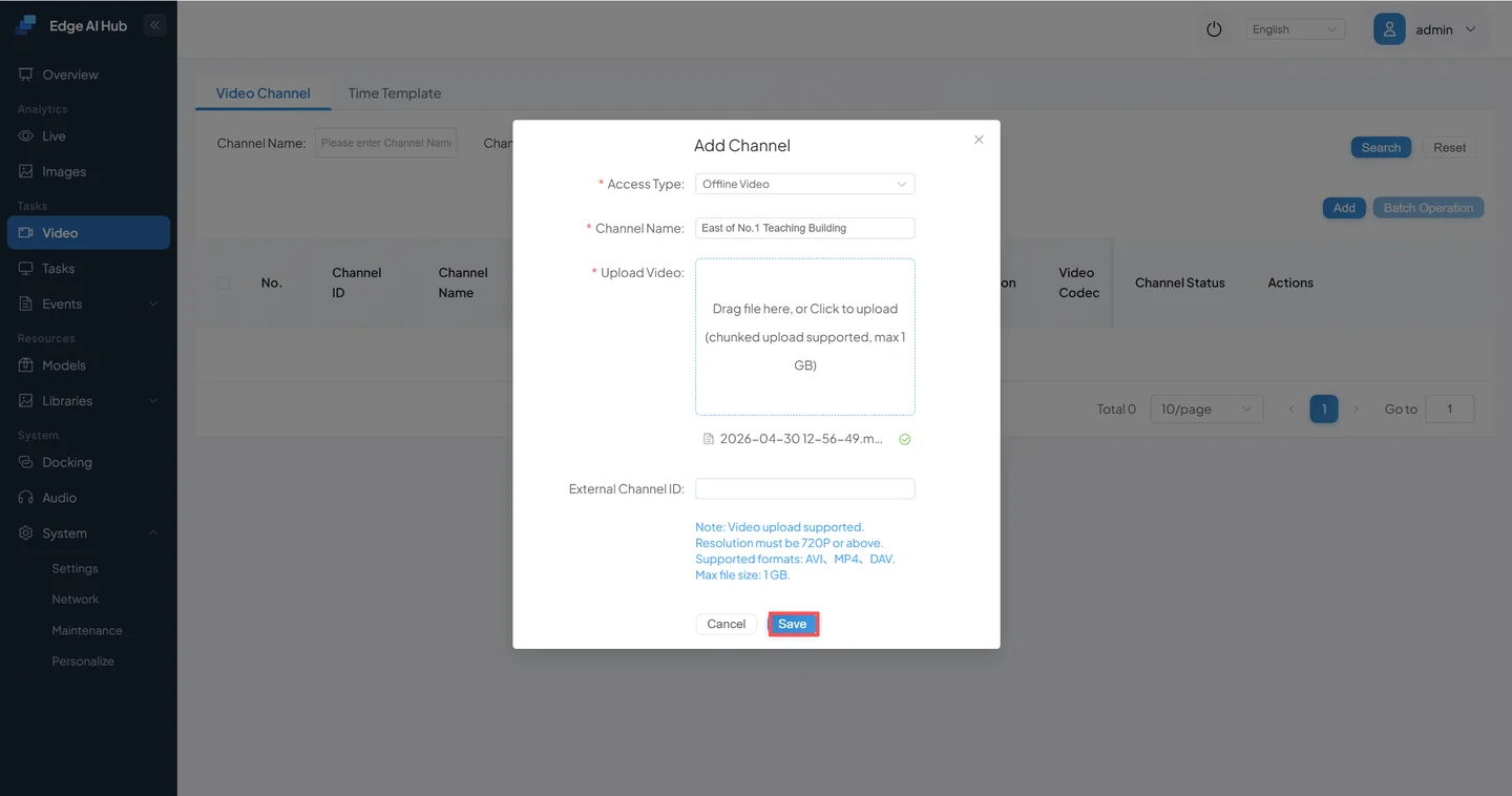
Success condition: the new channel appears without a persistent connection, upload, or decode error.
A camera is optional at this stage
After the first detection works, replace the offline video with an RTSP/RTSPS source. A local sample removes network, credential, and camera-codec differences from the initial system test.
4. Create the First Detection Task
Open Scenario Task Assignment from the new channel's action area.
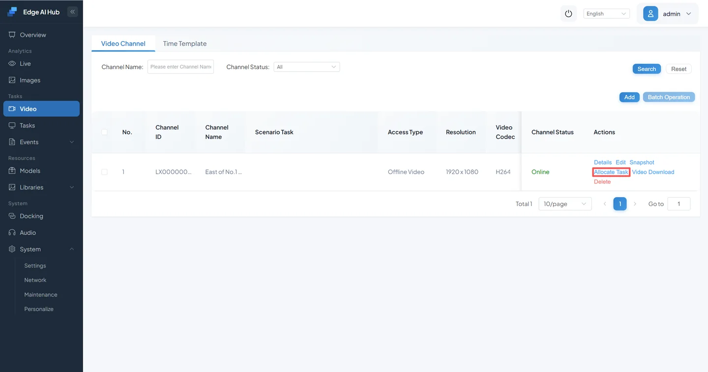
The page has three responsibilities: available algorithm services, services assigned to this channel with start/stop actions, and the selected service's region, parameters, and running strategy. Exact layout positions can change, but these responsibilities remain.

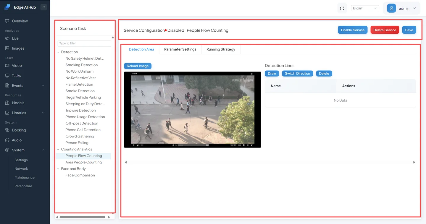
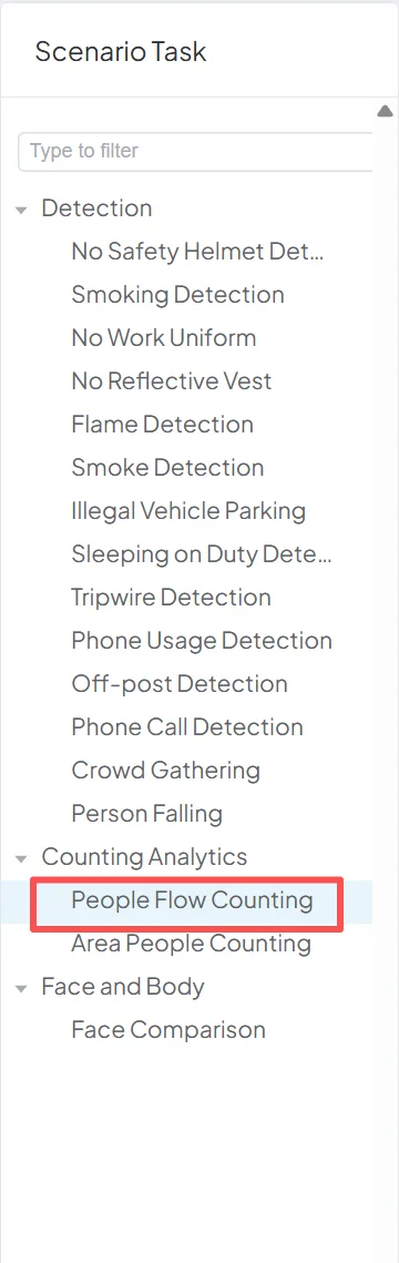
Select No Safety Helmet from the available services.
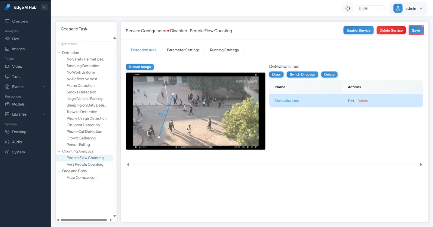
Under Detection Area, cover the main work area in the frame.
Keep the built-in parameters and running strategy for the first test.
Click Save. Saving associates the task with the channel and starts analysis.
Return to Video Access and confirm that the channel is enabled.
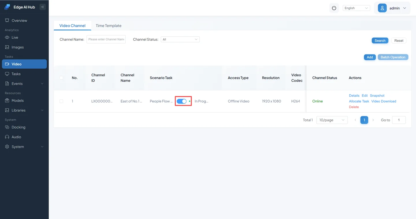
Success conditions:
- No Safety Helmet is assigned to the channel;
- the run switch is on or the status is In Progress;
- no persistent startup failure appears.
5. Verify the First Detection
5.1 Live Display
Open Live Display. It normally contains the channel list, the video and algorithm-overlay area, and a live event list. Single-view and multi-view layouts may be available.
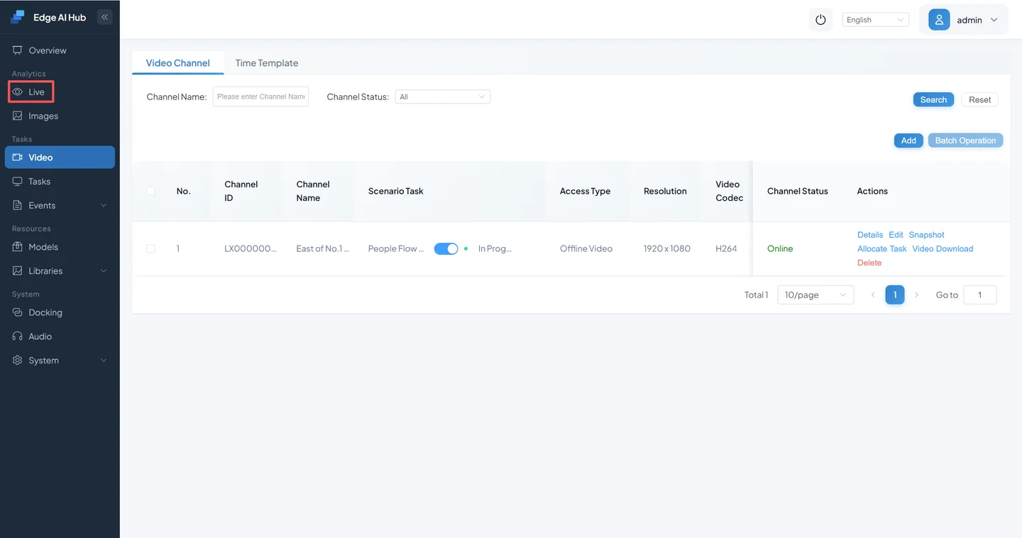
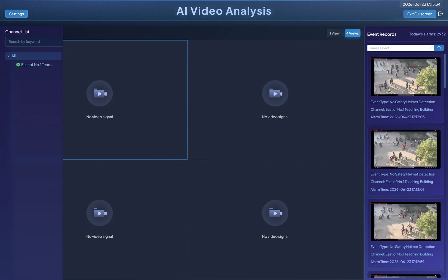
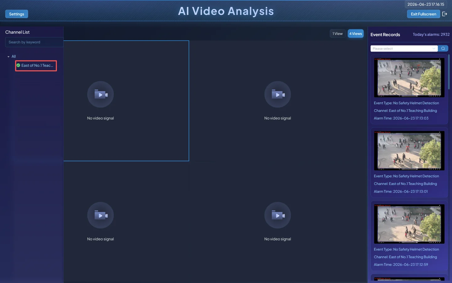
Select the new channel and allow time for playback and model initialization.
Select the algorithm overlay to display. Visible output depends on the Pipeline's detection, tracking, rule, and rendering capabilities.
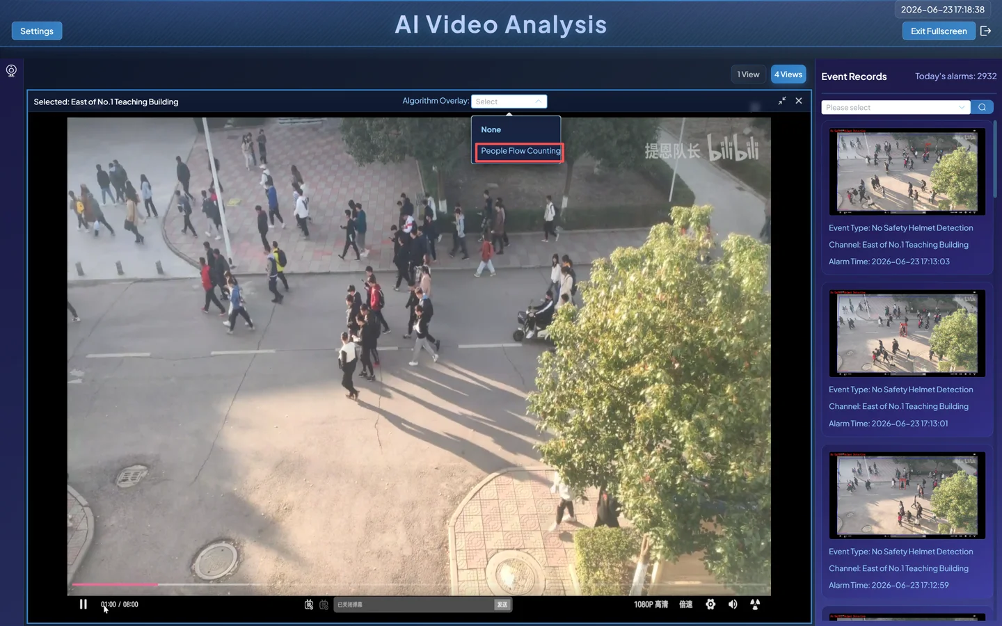
The safety-helmet sample should look similar to this:
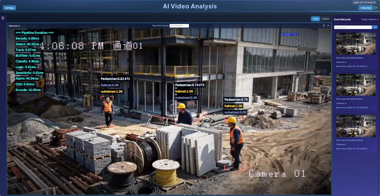
Acceptance conditions:
- video keeps playing;
- the matching boxes, labels, tracking IDs, algorithm state, or counts appear;
- the channel can be reopened after refreshing the page;
- resources do not remain saturated and the channel does not repeatedly restart.
5.2 Event Center
Open Event Center and query by channel, service, and time range. An event is created only when the image matches the detection condition and also satisfies alarm duration, count, interval, and deduplication rules. “Boxes are visible” and “an event exists” are separate checkpoints.
Additional: build a Sophon upgrade package from source
To build an upgrade package from source, select the target chip with the --chip <model> option at the repository root:
# BM1688
./scripts/docker-compose.sh -f docker-compose.sophon.yml run --rm cosmo-sophon-package --chip bm1688

# CV186X
./scripts/docker-compose.sh -f docker-compose.sophon.yml run --rm cosmo-sophon-package --chip cv186x

find build_output/public-runtime -mindepth 2 -maxdepth 2 -type f -print
Omitting the chip argument defaults to bm1688. The build script selects the matching model resource directory; you do not need to provide a model path.
The model resources in the package must match the target chip. BM1688 and CV186X artifacts are not interchangeable.
Use the one package name reported by the build for installation. To install it over SSH on a prepared Sophon Linux device, follow the Deployment Guide: SSH Installation Path. That section is the single source of truth for transfer, extraction, installation, reboot, base-system prerequisites, and recovery boundaries.
When CosmoEdge is already running, you can instead open System Management → System Maintenance → Software Upgrade and upload the same package. Keep power connected during installation. After reboot and sign-in, verify that Software Version matches the package version. The SSH installer targets a Sophon device with its base Linux system already prepared; it is not an OS-image installer for arbitrary blank hardware.
6. Complete Additional Example: People Counting
This section restores the complete people-counting workflow. It explains how a tripwire, direction, tracking, and count results fit together. If People Counting is not present in the current resources, finish the safety-helmet acceptance first, then use Pipeline Orchestration to confirm that the required template and model have been imported.
6.1 Prepare the Channel and Select the Service
- Use a video of people crossing a fixed point from the repository's
v1.0-videostag or another sample you are authorized to use. - Create an offline channel as described in Section 3, for example “Building 1 East Entrance.”
- Open Scenario Task Assignment and select People Counting under Counting Statistics.
6.2 Draw the Tripwire
The key region for people counting is a directional line, not a polygon:
- Draw: click the start point and the end point in the frame;
- Switch Direction: change which crossing direction is interpreted as entry or exit;
- Delete: remove an incorrect line before drawing again.
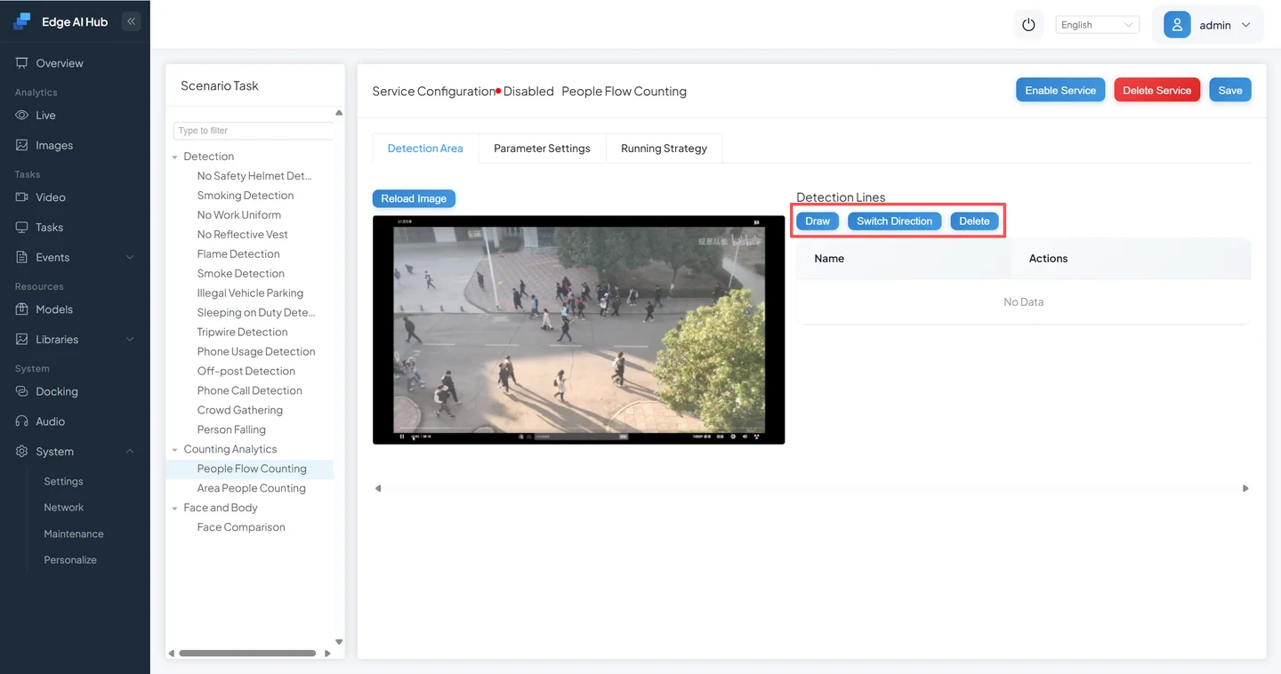
Click Draw, then click twice in the business-relevant location to set the start and end points. The arrow separates entry from exit.
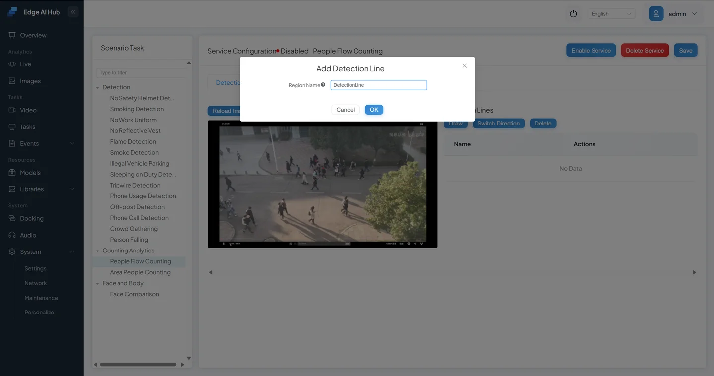
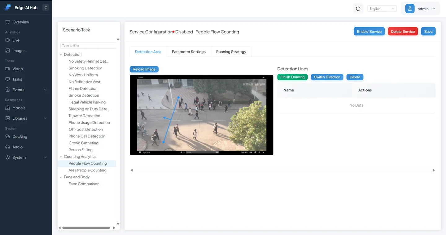
When position and direction are correct, click Finish Drawing.
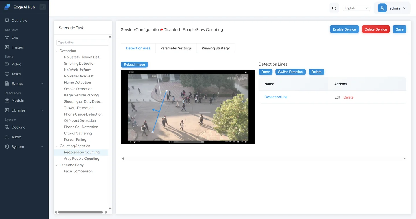
6.3 Set the Offline-Video Running Strategy
To observe the same sample repeatedly, use Offline Video Play Count. The form accepts 0–100: 0 loops indefinitely, while 1–100 is the total number of plays.
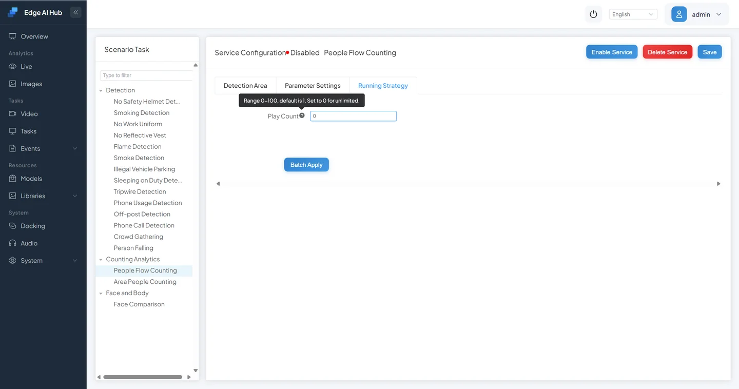
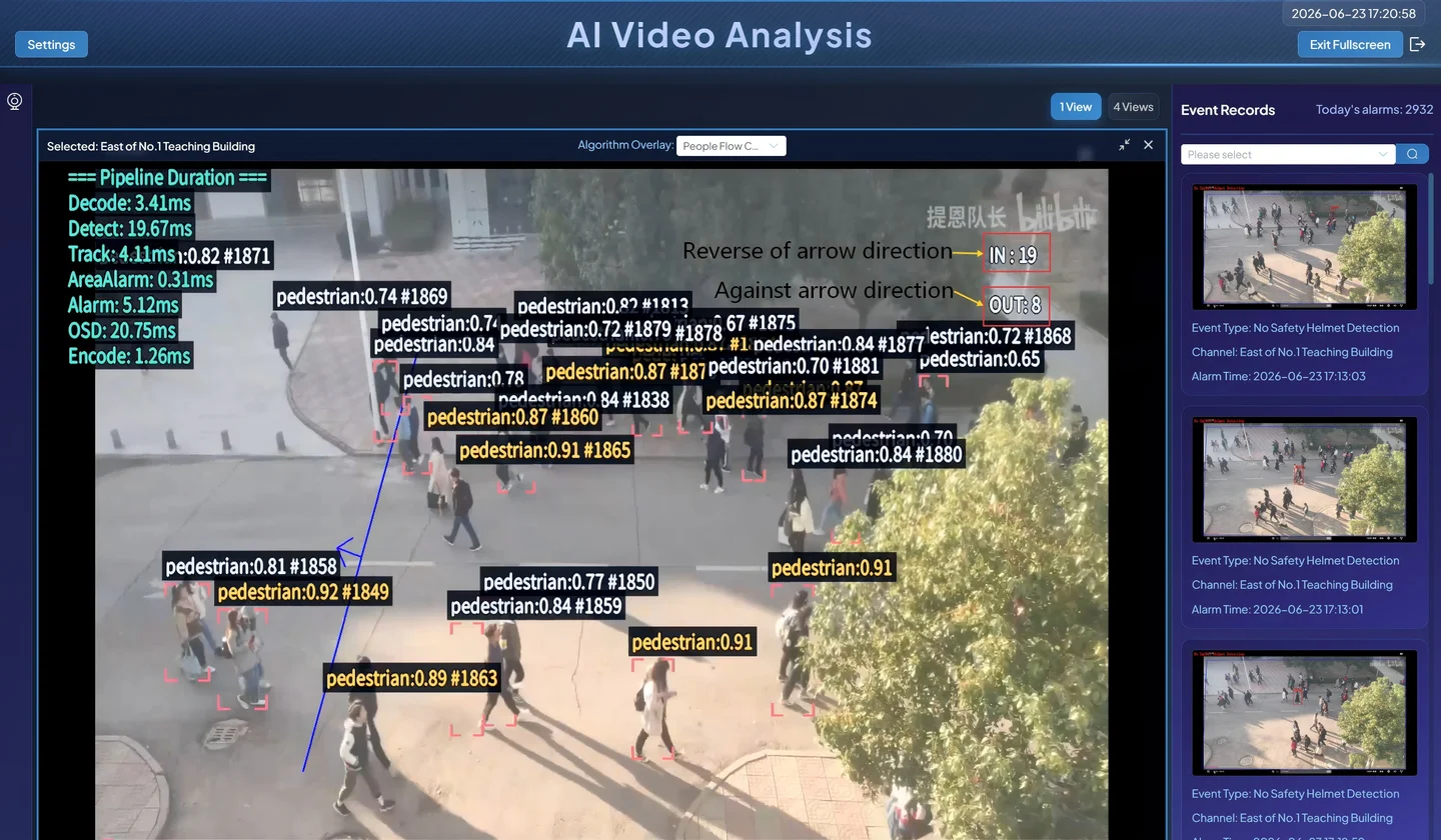
Save and confirm that the channel is In Progress. In Live Display, select the channel and the People Counting overlay. A working result can include:
- pedestrian class and confidence;
- a tracking ID;
- relevant algorithm-node timings;
INandOUTcrossing counts.
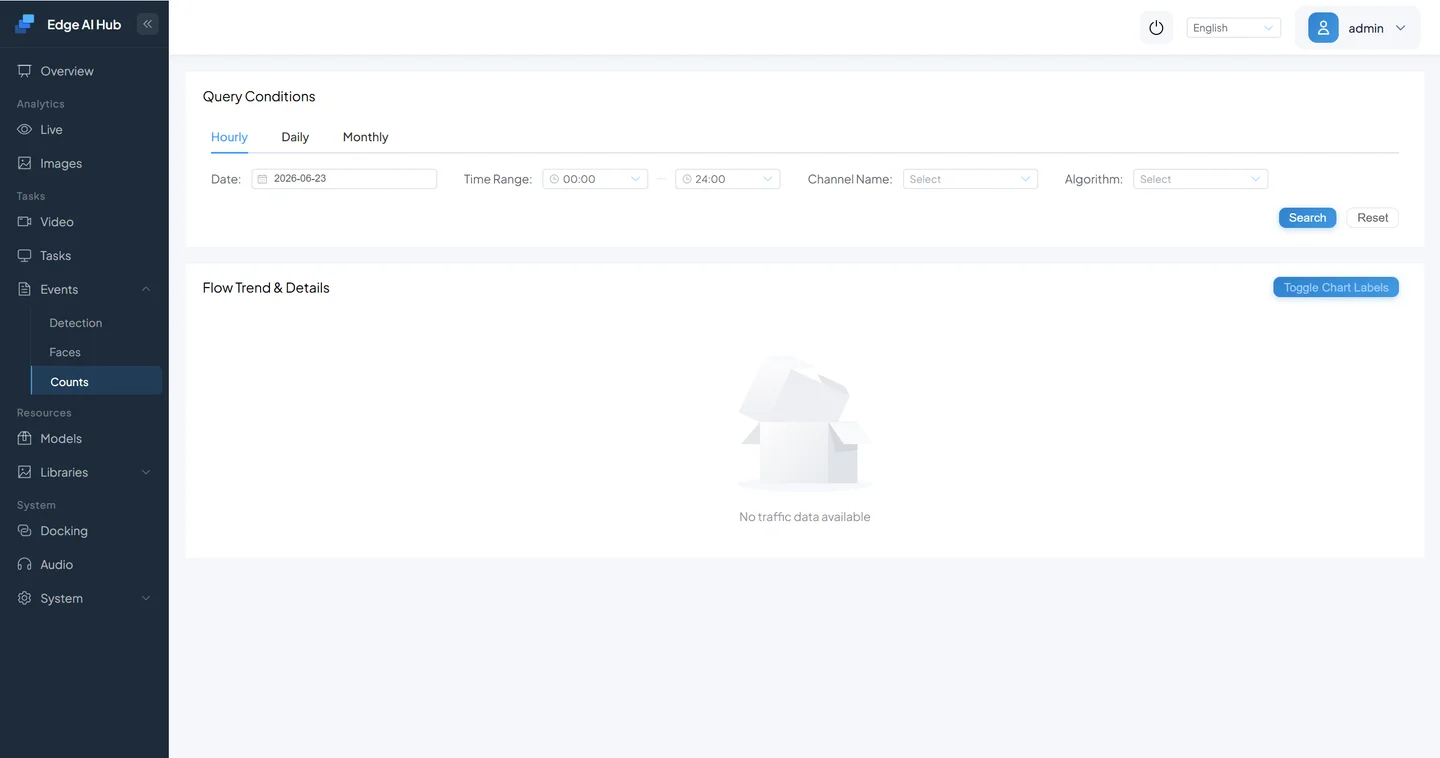
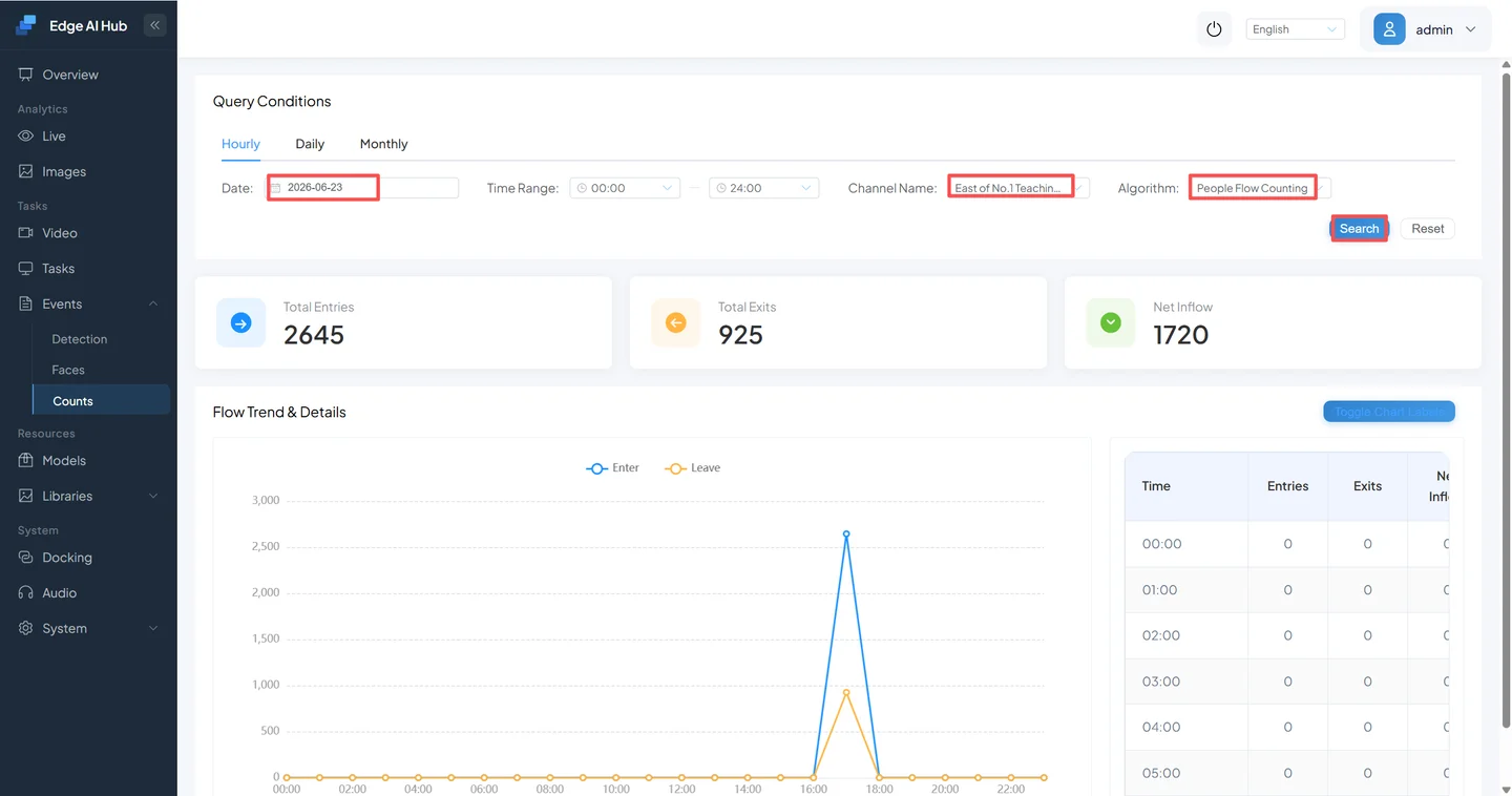
Finally open Event Center → Counting Statistics and query by channel and service. Exit traffic normally corresponds to OUT, while entry or net inflow is represented by IN; use the current template and field labels as the source of truth.
7. First-Detection Acceptance Checklist
- [ ] Deployment method, current access address, and validation time are recorded.
- [ ] x86 services are
Up/running, or the edge device has normal power and network state. - [ ] When using the default device IP, the computer has a non-conflicting
192.168.100.x/24address. - [ ] The system is accessible, the default password has been changed, and device time and time zone are correct.
- [ ] After moving the device to the production LAN, the new address can be used to sign in.
- [ ]
Safety Helmet.mp4exists as an offline channel. - [ ] No Safety Helmet is assigned and the channel is running.
- [ ] Live Display plays continuously and shows algorithm output.
- [ ] A clip that matches the rule creates a queryable event in Event Center.
- [ ] If the additional exercise was completed, tripwire direction matches the
IN/OUTresults.
Complete every item that applies to the selected deployment path before treating the first detection as accepted.
8. Troubleshooting
Containers Do Not Start
Check in this order:
docker compose -f docker-compose.x86.yml ps
docker compose -f docker-compose.x86.yml logs --tail=200
docker system df
Confirm that Docker is running, disk space is available, and port 8080 is free. See Troubleshooting for the broader diagnostic entry point.
The Default Device Address Does Not Open
- Confirm that the computer uses an unused
192.168.100.x/24address, not192.168.100.1. - Temporarily disable VPNs or proxies for that adapter and check whether another route owns
192.168.100.0/24. - Connect the computer and device directly, then recheck the cable and link indicator.
- Open
http://192.168.100.1; do not force HTTPS. - If the address was changed earlier, use the recorded address instead of starting with a factory reset.
The Device Is Unreachable After an IP Change
Move the computer to the new device subnet and retry the new address. Check subnet mask, gateway, and address conflicts. If neither the old nor new address is reachable, preserve the current state and use the delivery manual's console, display, or maintenance path to inspect the network settings before power cycling repeatedly or resetting the device.
The Sign-In Page Does Not Open or Authentication Fails
- For x86, confirm that the browser uses host port
8080, not an internal container port. - For remote access, check the host IP, firewall, and subnet.
- Use
admin/adminonly for a first sign-in. If the password has changed, use the new password instead of rebuilding containers. - If sign-in works but timestamps or sessions behave abnormally, correct device time first.
The Saved Video Has No Picture
Diagnose in the order “file readability → channel state → decode logs → algorithm state”:
- Start with the repository MP4 instead of introducing RTSP network variables.
- Confirm that upload completed and the channel is enabled.
- Check service logs for file-read, codec, or decode errors.
- If video is present but overlays are absent, confirm that the scenario task was saved and started.
Live Detections Appear but No Event Is Created
This is usually not a connectivity problem. Confirm that the clip actually matches the business rule, then inspect alarm interval, alarm count, detection duration, and static-target deduplication. The next guide explains these settings.
People-Counting Direction Is Reversed or Counts Do Not Update
- Use Switch Direction to correct the tripwire arrow.
- Confirm that people cross the line completely instead of moving only on one side.
- Confirm that tracking IDs remain stable across the crossing and do not reset because of occlusion or a very small target.
- Run the query again to refresh the result, and recheck the selected channel, service, and time range.
Next Step
Continue with Scenario Task Configuration to set detection areas, parameters, running strategies, and alarm rules precisely.